|
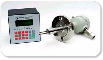
Thermal Dispersion type Flow Metering system-845T |
|
| |
|
|
| |
| Introduction |
Pantech Instruments, an eminent manufacturer of process control instruments since last 15 years, has developed this type of meter by their indigenous R&D efforts. The flow meter is definitely a state of technology product, totally in line with all the industrial and gas standards. |
|
|
| |
| Principle of Operation |
 The thermal sensor uses the principle of heat dissipation. A heated sensor is inserted into the stream of gas flow. The cooling effect of the gas is measured, transduced and interpreted as flow. The cooling effect is a direct function of the heat transfer that takes place due to the flow of gas. The heat transfer in turn is a direct function of the velocity as well as density of the process gas. Hence variations in temperature and pressure in the process gas are automatically compensated. For all practical purposes the output signal obtained is pressure and temperature compensated “massflow” signal. Thus the compensated flow independent of pressure and temperature variation is indicated without need for any separate transducers for the same.
The user friendly features and main advantages of this flow meter are : |
| In areas of flow metering, where the process gas pressures are very low, conventional flow metering techniques present a no. of limitations. In case of Thermal Mass Flow meter, upstream pressure required is very low because pressure drop across the sensor is negligible. Hence it works in place where Orifice/Rotameter type flow meters have failed. For this reason it is ideally suitable for very low height gravity feeds, reflux lines, condensers/accumulator systems etc. |
| There are no moving parts in the system. So choking, jamming effect are not observed even after very long run of the meter. There is no need to carry out periodic cleaning unless the fluid is very viscous or dirty. |
| There is no need to measure variations in pressure and temp. because the basic principle allows us to get a compensated output for both the readings. This substantially reduces the total cost of the installed system as well as the maintenance, troubleshooting time, spares inventory and frequent calibrations. |
| Flow ranges available are very large, typically 1:100 and more, as compared to 1:3 to 1:10 by orifice type flow meters and rotameters. |
| As per recent requirements, hazardous service installations should have minimum possible threaded/flange joints. Unlike the Orifice type ( 6-8 joints ) and rotameter type ( 2 joints ), this requires only one joint, either threaded or flanged. This makes it a very safe and desirable choice. |
|
| |
| Sensor Operation |
| The sensor has a reference element, measuring service temperature. The other element is heated electronically. The heat carried away by the fluid depends on the molecular flow across it. The electronic control circuit measures and controls so that there is a constant difference between the fluid temperature and the temperature of the heated element. The flow rate is displayed in unit of mass per time as per the calculations now. The totaled mass flow per desired elapsed time is also displayed hence. |
| |
| Sensor Installation |
The sensor has a 1.5” flanged connection. It is to be fixed on the pipe line nozzle horizontally with heated element ( indicated by a punched depression on the flange ) on top and cold or reference element below it, as shown in fig. 1.
The sensor has six terminals. They are to be connected to the flow indicator cum totalizer as show in fig.2. |
| |
SPECIFICATIONS : |
| Instrument |
:: |
Thermal Mass Flow meter. |
| Service |
:: |
Natural Gas / LPG |
| Range |
:: |
0 to 600 cubic meter per hour |
| Accuracy |
:: |
+/-1% of the range |
|
Sensor : Hermetically sealed. No moving part in it. |
| |
| Technical Specifications : |
| Type |
:: |
Microprocessor based Instrument |
| Input |
:: |
Signal from the Sensor supplied |
| Display |
:: |
On LCD panel of display size - 20 Characters * 4 lines
Continuous display : Date, Time, 4 digit Flow rate, 8 digit Totalized |
| Key in param. |
:: |
Clients Name, Service Fluid/Gas, Pressure details, Temp. details. |
| Security |
:: |
Password Protected – User level, Engineer level |
| Data Logging |
:: |
The instrument shall incorporate last 96 values of flow data � Date,
Time, Flow rate, Totalized flow for a particular time interval set. This
Data can be printed on a dot matrix printer.
Data entry : Front side, 16 keys keypad. |
| Power |
:: |
24 V DC, 300 mA regulated type. |
| Enclosure |
:: |
Sheet Metal, Powder coated, IP65 level
Dimensions : 144*144*110 ( Panel mounted ) |
| |
|
|
Battery backup: Provided ( Optional feature ) |
|
| |
| |
 |
| |
| |
|