|
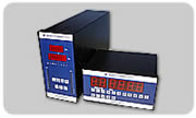
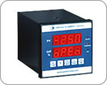
Pantech's Programmable Universal/Predefined input Scanner, model 891 is an ideal instrument for providing indication , controlling set points for various multiple processes and logging the data in its memory bank. It is designed to accept various process inputs (Current, Voltage, RTD, and Thermocouple) simultaneously (or predefined) with facility of all inputs onboard field configuration, calibration and displaying the same. Data structures of all the channels and relays is stored inside the memory chips of instrument. These stored in data can be communicated to a higher device like a desktop through RS232/485 communications. The high end interactive software on the PC allows the user to download these days / preview them with different tabular or graphical modes etc. Two scanning modes are provided AUTO/MANUAL. It is normally designed to accept UPTO 32 different channels simultaneously. The instrument allows CHANNEL TO GROUP fixings, RELAYS to GROUP fixings . Detailed functions and configurations regarding these are explained beneath. The model is also equipped with an optional 4 analog outputs facility (Isolated or non-isolated). The model has optional in built RTC for providing timed data. The scanning time can be adjusted from 1 second to 99 seconds maximum through front keys. Unused channel SKIP facility is also provided in all versions. It can be optionally equipped with serial/parallel communication facility of different open protocols. The high end microprocessor program ensures the best and easiest possible user interactive modes. The EASE felt by the user in configuring the scanner / data logger is the real essence of product. Low drift precession components are used for long term accuracy of the instruments. All instruments undergo a burn-in for better reliability.The instrument is available in different formats and sizes. Magnified and classified Informations regarding the instrument are as below :-
-
Based on the no. of input channels and contact outputs, the scanner/data logger electronics is divided into two basic versions –
-
Maximum No. of input channels – 32 // Maximum No. of relay contact outputs – 16 – Ver.1
-
Maximum No. of input channels- 24 // Maximum No. of relay contact outputs – 32 – Ver.2
The user application must confirm with any of the two or both of the above versions. Requests beyond the above versions are subject to factory confirmation only.
-
The DATA LOGGER stores all the data in FIFO manner ( FIRST IN FIRST OUT ). The high memory chips allows the data storage capacity to maximum of 5000************** records. The user is allowed to choose in from various options of data logging. The user can choose to log in data for a selected channel only and exclude some channels from this.
-
All the data from the instrument is taken to the desktop by RS485/RS232 communication ports. These data can be interpreted in many graphical formats by the higher layer user interactive softwares.
-
The instrument also allows a perfect CHANNEL to GROUP mapping & RELAY to GROUP mapping. The user must understand this feature which empowers him to configure the scanner for any logics. Let us see an example to understand this feature –
* Suppose the User opts for 16 channel and 16 relay scanner. ( Both version-1&2 are satisfied )
* Now the user can form maximum of 16 groups ( No. of groups <= No. of channels ). At this point the user is
required to decide with no. of groups he is going for. ( This depends on his application ).
* Now suppose the user selects for 8 groups to be formed ( grp1…grp8 ).
* Now each of the channel can be assigned to any of the 8 groups. Each of the grp1…grp8 can have any no. of channels. ONE CHANNEL ONCE ASSIGNED IN ONE GROUP, CANNOT BE ASSIGNED TO OTHER.
Here say that for example.. we do as :- ( grp1 = ch1, ch2 /// grp2 = ch3, ch4 // …. Grp8=ch15,ch16 ).
So now after these configurations we are having 8 groups in our hand and 16 un-assigned relays.
* Now each of the relay is assigned to any of the existing 8 groups. Note that one relay once assigned to a group
cannot be assigned to other. Each of the rly1…rly16 can be assigned to any of the grp1..grp8. Here say for
example that we do as :- ( rly1 = grp1, rly2 = grp1, rly3 = grp2 , rly4 = grp2…..rly15 = grp8, rly16=grp 8 ).
This way we see that each of the relay is configured to work on a specific group. The relay can also be
Configured to work on “AND” or “OR” logic for the assigned group. In above example hence we see that for
each couple of channels, we have assigned a couple of relays only.
* Above is just an example of possible usage of CHANNEL to GROUP mapping // RELAY to GROUP mapping.
* Note that the user can do any type of configurations by using these functions. As of in above example only for instance, the user can configure so that all the 16 relays operate on one channel only // or say that 8 relays operate on channe-1 and rest 8 relays operate on channel-16 // or say that relay 1 operates for all the 16 channels and rest relays are unused…etc. Using this MAPPING functions to its full, is a virture of user’s creativity now.
* All contact output related functions like : SETPOINT, ALARMTYPE, HYST. Can be configured for.
-
The RESPONSE time dedicated to each of the channel is in microseconds. This is possible because of the high speed microprocessor chips on board.
-
UNIVERSAL / PREDEFINED type inputs possible for each of the channel. Note that each of the channel is required to be calibrated individually .
-
All configurations, Calibrations, Setting of scanner functions like : A/M, SKIP, SCANTIME etc are done by front fascia keys only.
-
4 ISOALTED Retransmission outputs on selected input channels is possible.
|